New Features in Router-CIM 2020
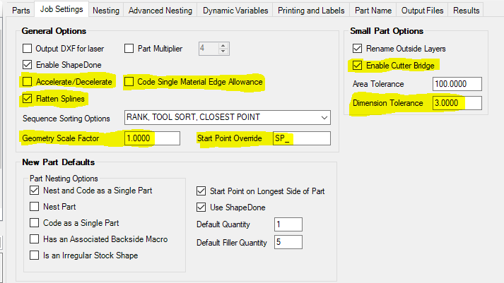
What is new in the Job Settings Tab:
- Accelerate/Decelerate
- Enables the Acceleration/Deceleration option when running Automation Suite. See Acceleration/Deceleration in the help manual for more information on this feature.
- Flatten Splines
- Previously *NOFLATNSPLINE* - Uncheck this box if you do not wish to use FLATTEN on splines during Automation
- Geometry Scale Factor
- Previously *SCALEAUTOMATIONGEO* - Will scale all geometry by the factor input into this field. Useful for converting drawings from inch to metric and vice versa
- Small Dimension Tolerance
- Previously *SMLSIZE* - Adds another condition for a part to be considered “small”. If a part has an X or Y size smaller than the value input here, it will be considered a small part and get its outside layer renamed accordingly
- Start Point Override
- Previously *SPOVERRIDE* - Used to manually pick a start point during Automation run. Set this field to “SP_” (or any 3 characters) and then rename your layers with that prefix. Once that has been completed, you will need to change the DOIT file layer to knowledge associations in order to cut the layers properly. You can then run the job, Router-CIM Automation Suite will stop on the geometry on those layers and prompt you to pick a start point.
- Code Single Material Edge Allowance
- Previously *YESEDGE* - This feature allows for a part that is set to 'Code as Single Part' to have the individual NC code file produced with the Material Edge Allowance that is set up in your Materials Database. Check this box to allow 'Code as Single Part' to offset the part just like what would happen if the part is nested by the material edge allowance.
- Enable Cutter Bridge
- Previously *BPP* - Allows the use of the “Cutter Bridge” field under the “Tool Information” section in a knowledge. If this box is checked and a number is in the “Cutter Bridge” field under the “Tool Information” section, an additional offset will be added to the outside of the part when nested.
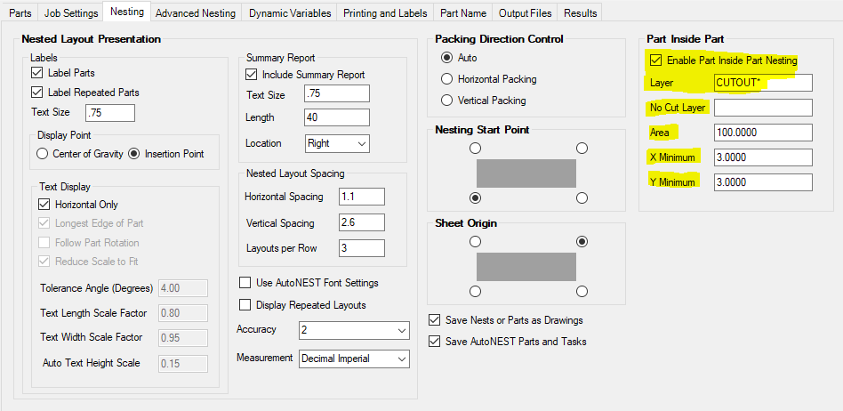
What is new in the Nesting Tab:
- Part Inside Part Nesting
- Enable Part Inside Part Nesting
- Toggle on and off to activate or deactivate this feature
- Layer
- Previously *PIPLAYER* - This is the layer name you want to use for parts to nest inside. For instance, with Solid-CIM this would be “CUTOUT*”.
- No Cut Layer
- Previously *PIPNOCUTLAYER* - This is the layer name you want to use for parts to nest inside when this layer is not actually cut in the nest
- Area
- Previously *PIPAREA* - This is the minimum area the geometry must be in order for nest to place parts on it. So, all cutouts that have at least this much area will be considered for PIP nesting.
- X Minimum
- Previously *PIPXMIN* - The minimum size in X for a part to be considered for PIP nesting.
- Y Minimum
- Previously *PIPYMIN* - The minimum size in Y for a part to be considered for PIP nesting.
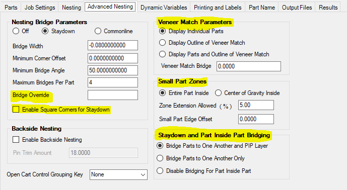
What is new in the Advanced Nesting Tab:
- Bridge Override
- Previously *BRIDGE_OVERRIDE* - Set this field in order to have the Staydown function not offset the tool path by the radius of the tool used. For example, if set to 0.0 this will mean that the Staydown tool path will be offset by 0.0 instead of offsetting by the tool radius in the STAYDOWN knowledge.
- Enable Square Corners for Staydown
- Previously *FORCESQUARE* - The Staydown geometry created by Router-CIM has the rounded corner function in use by default. In order to change this function, you need to check this box
- Pin Trim Amount
- Previously *PIN_TRIMAMT* - This value defines the extension amount of the pin trim cut in the Y axis during two-sided nesting
- Veneer Match Bridge
- Previously *CLUSTER_BRIDGE* - Used to override the Veneer Matching default of using the materials bridge width for part spacing
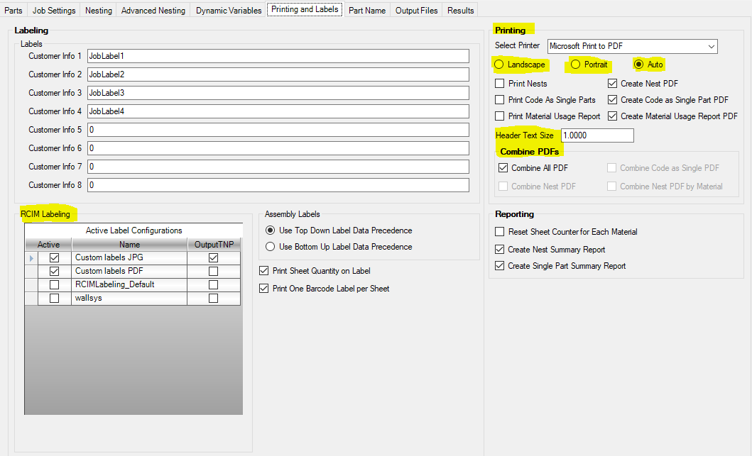
What is new in the Printing and Labels Tab:
- Rearranged tab to better group settings by functionality
- Header Text Size
- Previously *NTHEIGHT* - Defines the text height of the text above the nested sheet in the nested drawing that Router-CIM Automation Suite uses
- Plot PDFs
- Create Nest PDF
- Check box to create a PDF of the Nest during the job run
- Create Code as Single Part PDF
- Check box to create a PDF of each Code as Single Part during the job run
- Create Material Usage Report PDF
- Check box to create a PDF of the Material Usage Report during the job run
- Plot Direction – Defines the orientation for the print nest feature
- Landscape
- Portrait
- Auto
- Combine PDFs
- Combine All PDF
- All selected PDFs to be created will be included in 1 PDF file
- Combine Nest PDF
- All Nest PDFs to be created will be included in 1 PDF file
- Combine Code as Single PDF
- All Code as Single PDFs to be created will be included in 1 PDF file
- Combine Nest PDF by Material
- All Nest PDFs to be created will have 1 file per material in the job
- Create Single Part Summary Report
- Check this box in order to include the Single Part Summary in the Summary Report that is generated during job run
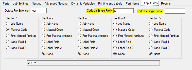
 What is new in the Output Files Tab:
- Code as Single Prefix
- Previously *SINGLE_PRE* - This field will be attached to the beginning of the file name for each Code as Single machine code file generated during job run
- Code as Single Suffix
- Previously *SINGLE_SUF* - This field will be attached to the end of the file name for each Code as Single machine code file generated during job run
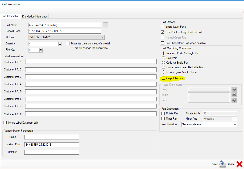
 What is new in Part Properties:
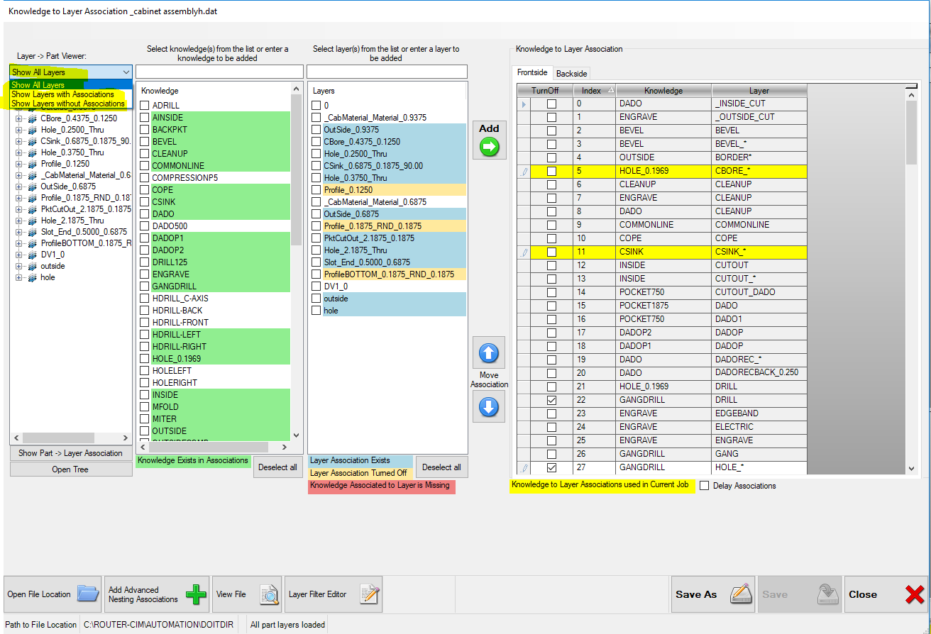
 What is new in DOIT Editor:
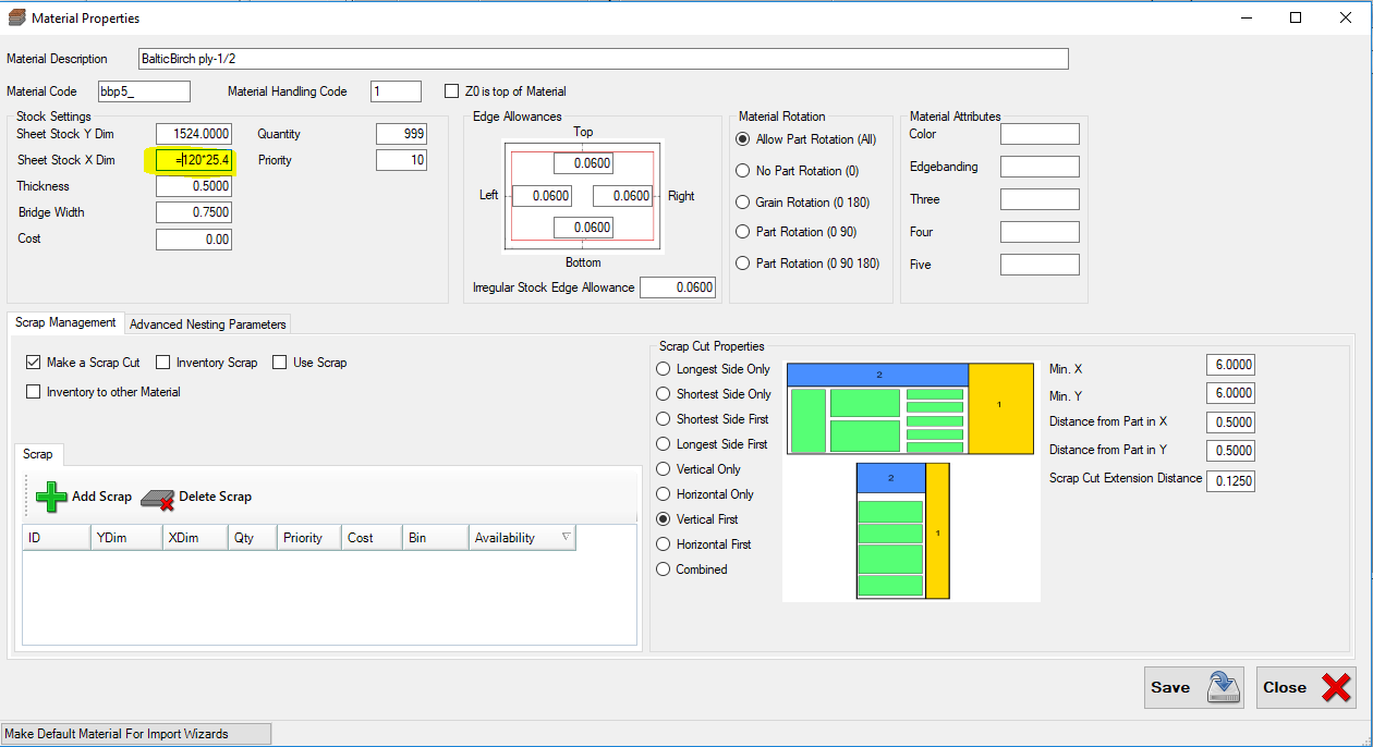
 What is new in Material Properties:
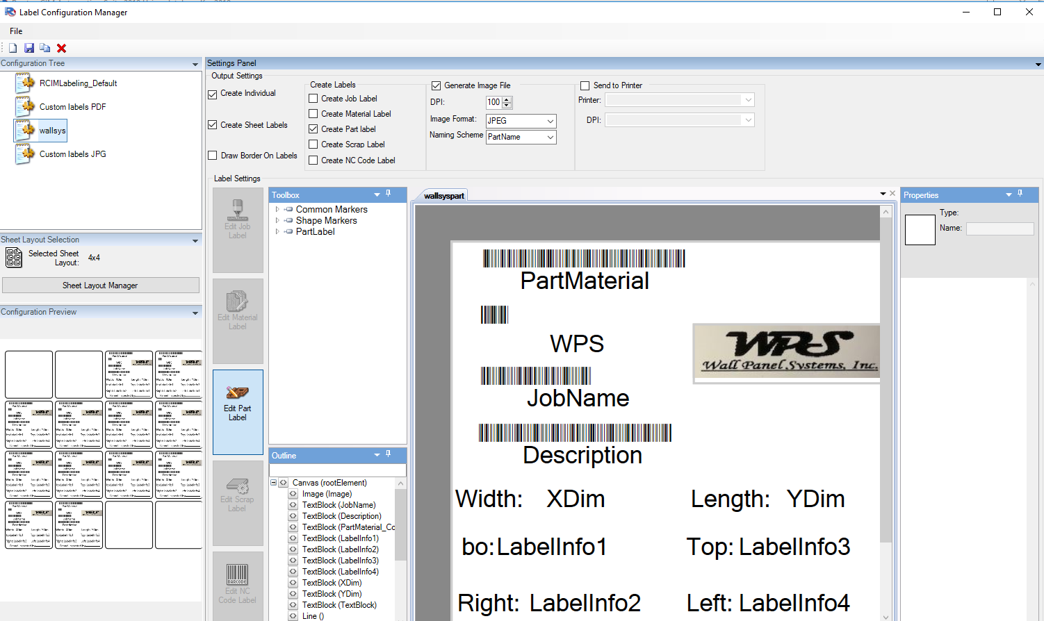
 What is new in Labeling:
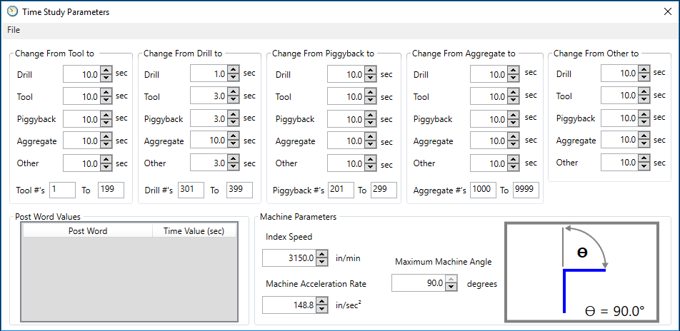
 New Cycle time parameters:
- Dial in the machine acceleration parameters for more accurate cycle times.
 What is new in the Main Control Panel Interface:
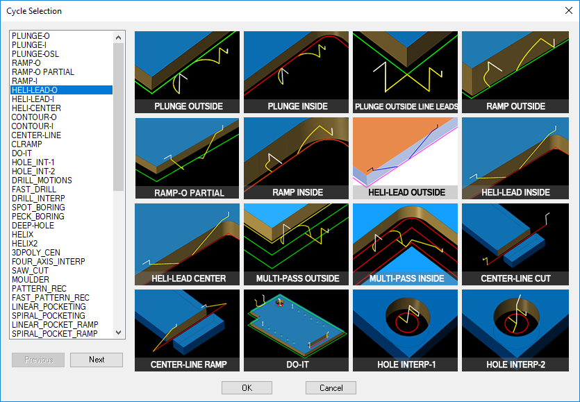
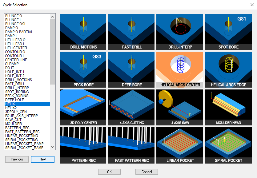
- Updated graphics for all cycles and command buttons
- Double-Click item to open help manual
- You can now double click the text of a setting and it will open the help manual straight to the correct location
- E.g. double-click “CRC Offset” and it opens the help manual and automatically navigates to the CRC Offset section
- Delete cycle parameters in the Cycle Information section
- In the Cycle Information section, use the arrow to open up the drop down menu, hover over the parameter you would like to remove, and press the “Delete” key
- Updated settings in the Cycle Information section
- Each cycle now has its own customized set of cycle settings in the Cycle Information column which contain only the settings applicable to the selected cycle
- Ramp Amount and Overlap Amount moved to Cycle Information section
- The Ramp Amount and Overlap Amount settings have been moved from the Knowledge/Settings section to the Cycle Information section and are only displayed on the cycles that they are compatible with
- Reset Cycle Settings to Default button
- A new button has been added to the Status Information section which allows you to reset all of the cycle settings in the Cycle Information to their default values
- Note: this button does not currently reset the Ramp Amount, Overlap Amount, or Corner Punch settings
- Error Checking
- There is now error checking that will alert the user if an invalid value has been entered in a field
- “Cutter Bridge” field under the “Tool Information” section in a knowledge. If this box is checked and a number is in the “Cutter Bridge” field under the “Tool Information” section, an additional offset will be added to the outside of the part when nested.
- Corner Punch is like a bubble fillet without having to draw a bubble fillet. The cycle extends the tool into a corner so that a mating sharp corner part will fit in there
What is new in the Tool Selection Interface:
- Can now filter the tool list based on Inches or Metric
- Added the capability to move tools around in the list using the Tool Order buttons on the right side of the interface
- Delete Tool button was added to be able to delete unwanted tools
What is new in the Knowledge Editor Interface:
- Added buttons to be able to Export and Import Knowledges from a CSV file
- This enables the user to be able to make changes to numerous Knowledges at once
New Ramp-Outside Partial Cutting Cycle:
- Allows you to have a helical lead-in and lead-out from a point perpendicular to the part
- See help manual for further details about new cycle

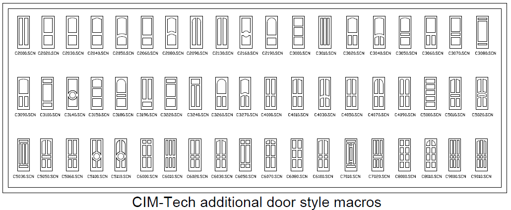
 All new parametric door macros included in Router-CIM 2019!